Peugeot 308: Removing - refitting : Clutch mechanism - Pushed type (Demonstration video)
ESSENTIAL : Observe the safety and cleanliness instructions
 .
.
CAUTION : In order to improve the centring of the friction plate and to eliminate engine hesitation, vibrations and noise, compress the clutch mechanism when tightening the bolts ; Using the tool [0217].
CAUTION : If replacing the clutch mechanism or clutch disc ; Always replace the clutch bearing, the bearing guide, the clutch fork and the clutch fork ball joint.
1. Demonstration video
Consult the videos available at the following URL addresses.
| operation | Link |
| Removing - refitting | http://public.servicebox-parts.com/dtt/AP/Diag_AP/donnees/Embrayage/video-embrayage-ML6_1.mp4 |
2. Replacement of parts in all cases
| Description | Quantity |
| Clutch mechanism bolt | 6 |
| Gearbox centring pin | 2 |
| Clutch bearing (*) | 1 |
| Clutch release bearing guide (*) | 1 |
| Clutch fork (*) | 1 |
| Bearing (Clutch fork ball joint) (*) | 1 |
| Clutch fork ball joint (*) | 1 |
| (*) If replacing the clutch mechanism or clutch disc | |
3. Tooling
N.B. : Use the appropriate mandrel according to the tables below ; The tool [0217-B2Z] can be replaced with the standard tools.
| Tool | Reference | Description |
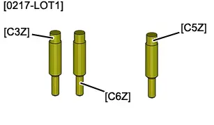
| [0217-LOT1] | Clutch disc centralising mandrel |
| [0217-C3Z] | Clutch disc centralising mandrel | |
| [0217-C5Z] | Clutch disc centralising mandrel | |
| [0217-C6Z] | Clutch disc centralising mandrel | |
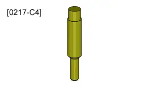
| [0217-C4] | Clutch disc centralising mandrel |
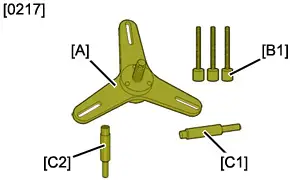
| [0217] | Clutch compressor with take-up of play |
| [0217-A] | Plate | |
| [0217-B1] | Rod | |
| [0217-C1] | Clutch disc centralising mandrel | |
| [0217-C2] | Clutch disc centralising mandrel | |
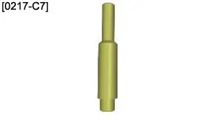
| [0217-C7] | Clutch disc centralising mandrel |
| [0217-C8] | Clutch disc centralising mandrel |
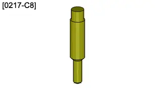
Clutch centring drift
| Engine version | [0217-C1] | [0217-C2] | [0217-C3Z] | [0217-C4] | [0217-C5Z] | [0217-C6Z] | [0217-C7] | [0217-C8] |
| DV4 | BE | MA/MAP | ||||||
| DV4 C | MA/MAP | |||||||
| DV5R | ML | ML/MB/BE | ||||||
| DV6 Euro4 | MCM | MCP/ BE | BE | |||||
| DV6UC | BE | |||||||
| DV6DU (M) | BE | |||||||
| DV6C (M) | ML | BE | MCP/MCM | |||||
| DV6D (M) | BE/MCP | MCP | ||||||
| DV6E (M) | BE | |||||||
| DV6F | ML | BE/MCP/ML | ||||||
| DW10 | ML/BE | MCP | MCP | |||||
| DW12 | ML | W6MBA | ||||||
| 4B12 | W5MBA | |||||||
| EB0 | MA | |||||||
| EB2 | MA/MAP/BE | |||||||
| EB2M | MA/MAP | |||||||
| EB2F | MA/MAP | |||||||
| EB2FAMK | MA | |||||||
| EB2DT | BE | |||||||
| EB2DTS | BE | MCM | ||||||
| EB2DTSM | BE | |||||||
| EB2ADT/D | MB | |||||||
| EB2ADTS | MB | |||||||
| EC5 | MA | BE | ||||||
| EC8 | BE | |||||||
| EP3 - EP3C | BE/MA/MAP | |||||||
| EP6 - EP6C (M) | BE/MA/MCM/ MCP | |||||||
| EP6CDTR | MCM | |||||||
| EP6DTS | MCM | |||||||
| EP6CDT | MCP | MCM/MCP | ||||||
| EP6CDTX | MCM | |||||||
| EP6FDT | MCM | |||||||
| EP6FDTX | MCM | |||||||
| ES9 | ML | |||||||
| ET3 | MA/MAP | |||||||
| EW10 | BE/MCP | |||||||
| EW12 | BE | |||||||
| EW6 | BE | |||||||
| EW7 | BE | |||||||
| TU1 | MA | |||||||
| TU3 | MA/MAP | |||||||
| TU5 | MA/MAP | BE | ||||||
| SOFIM | MLGU5 | M40 | ||||||
| PUMA | MLGU5/MLGU6 | |||||||
| 1,3 DTE | MTM/MTA | |||||||
| N3 | C513 |
4. Clutch mechanism with wear adjustment
CAUTION : No resetting of the clutch wear adjustment is permitted.
Apply the additional procedure relating to the wear adjustment system on the clutch mechanism
 .
.
5. Removing
CAUTION : Any removal or refitting of the clutch mechanism with or without take-up of play (new or reused) must be carried out using the compression tool [0217].
Remove the centralising bushes .
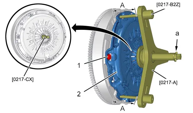
"a" : The central bolt of the tool [0217-A].
Fit the tool [0217-CX].
Remove the 3 bolts (1) (Every second bolt).
CAUTION : Some engine flywheels have open threads. Do not let the threads of the 3 retaining rods protrude when tightening ; Risk of distortion of the secondary engine flywheel.
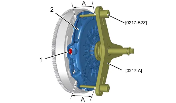
Putting in place of the tools [0217-A] and [0217-B2Z] :
- Screw in the retaining rods [0217-B2Z] by 5 turns in place of the bolts (1)
- Fit tool [0217-A] on tool [0217-B2Z]
- Align the tool [0217-A] with the clutch mechanism (2) ; Using the tools [0217-B2Z] (The dimensions "A" must be identical)
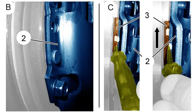
"B" Clutch mechanism (2) without access to the clutch disc (3).
"C" Clutch mechanism (2) with access to the clutch disc (3).
CAUTION : On compression of the clutch mechanism ; Do not pass the point of resistance when tightening the central bolt of the tool [0217-A].
Apply the procedure according to the assembly identified.
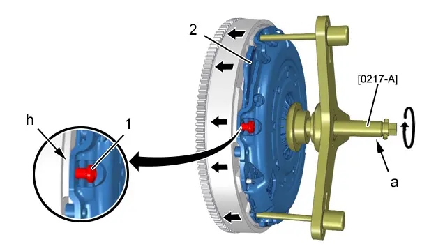
Assembly "B" : Compression of the clutch mechanism ; Using the central screw "a" of the tool [0217-A] :
- Bring the central bolt "a" of the tool [0217-A] in contact with the membrane of the clutch mechanism ; Without compressing
- Compress the clutch mechanism (2) ; Tighten the central bolt "a" by 3,5 turns maximum
Assembly "C" : Compression of the clutch mechanism ; Using the central screw "a" of the tool [0217-A] :
- Progressively compress the clutch mechanism (2) (By one eighth of a turn) ; Apply slight force to the clutch disc (3) to check the rotation ; Using a thin, flat screwdriver
- If rotation is difficult or impossible, continue the clutch mechanism compression operation very gradually until it rotates (8 th turn on the bolt of the tool [0217-B2Z])
Remove the 3 remaining bolts (1).
Unscrew bolt "a" of the tool [0217-A] a few turns to release the tension of the clutch mechanism (2).
Remove :
- Tools [0217-A] and [0217-B2Z]
- The clutch mechanism (2)
- The clutch disc (3)
6. Preparation for removal
6.1. Check - Cleaning
Visually check :
- The flywheel face for damage or scores
- The flywheel for wear
- The condition of the starter ring gear
- The clutch mechanism (2)
- The clutch stop guide (depending on equipment)
- The ball joint connection and the clutch fork support zones (depending on equipment)
If there is oil in the clutch mechanism (2) :
- Check the condition of the crankshaft ring seal
- Check the condition of the input shaft ring seal
CAUTION : Do not reuse a clutch disc whose hub bears traces of corrosion or whose lining bears traces of grease.
Remove corrosion and grease from the following parts ; Using degreaser index "N1"
 :
:
- The clutch housing
- The input shaft
- The clutch stop guide (depending on equipment)
- The clutch fork (depending on equipment)
N.B. : In the case of significant corrosion, use a metal brush without damaging the parts.
6.2. Greasing
CAUTION : The greasing stage must be observed strictly.
CAUTION : Protect the interior of the clutch housing from splashes of grease.
Vehicles equipped with a gearbox that has a mechanical clutch bearing.
Grease the following components (Index "G14"
 ) ; Using a brush :
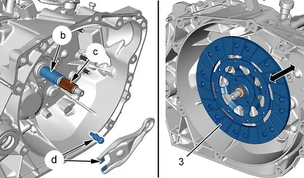
- The clutch stop guide (at "b")
- The gearbox input shaft splines (at "c")
Tighten the closing bolt (at "d") until the push rod is in contact with the clutch fork.
Vehicles equipped with a gearbox that has a hydraulic clutch bearing : Grease the splines of the primary shaft with (Index "G14"
 ) ; Using a brush (at "c").
CAUTION : Do not soil the clutch disc lining (3) ; Risk of slipping.
Put the clutch disc (3) in place on the grooved shaft and carry out several translational movements to distribute the grease.
Remove the clutch disc (3).
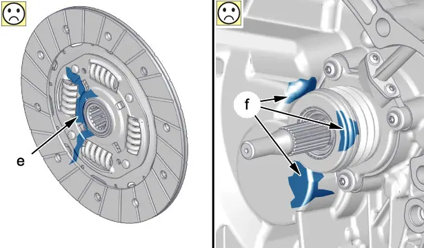
CAUTION : An excess of grease will contaminate the clutch friction plate and cause noise in neutral, slipping or juddering of the clutch.
"e" Traces of grease present on a clutch disc contaminated as a result of a surplus of grease.
"f" Traces of greases present on a clutch housing contaminated as a result of a surplus of grease.
CAUTION : Clean off all traces of grease which may splash onto the friction plate during rotation.
Use a cloth to remove any surplus grease on the following components :
- The top of the splines
- The ends of the splines
N.B. : The end of the input shaft.
The film of grease applied to the rotating components must be as thin as possible to avoid splashes.
7. Refitting
CAUTION : Observe the tightening torques.
CAUTION : The clutch mechanism (2) and the clutch disc (3) are paired at the factory and cannot be replaced separately.
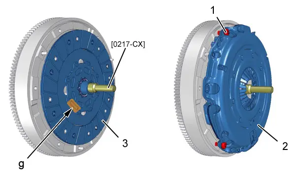
CAUTION : When refitting, position the face of the clutch disc (3) which bears the reference "PSA" or "GEARBOX SIDE", on the gearbox side (at "g").
Refit the clutch disc (3).
Centre the clutch disc (3) ; Using the tool [0217-CX].
CAUTION : Any removal or refitting of the clutch mechanism with or without take-up of play (new or reused) must be carried out using the compression tool [0217].
Refit :
- The clutch mechanism (2)
- The 3 new screws (1) (one screw out of two) ; Tighten by hand
N.B. : Do not remove the tool [0217-CX].
CAUTION : Some engine flywheels have open threads. Do not let the threads of the 3 retaining rods protrude when tightening ; Risk of distortion of the secondary engine flywheel.
Putting in place of the tools [0217-A] and [0217-B2Z] :
- Screw in the 3 retaining rods [0217-B2Z] by 5 turns in place of the bolts (1)
- Fit tool [0217-A] on tool [0217-B2Z]
- Align the tool [0217-A] with the clutch mechanism (2) ; Using the tools [0217-B2Z] (The dimensions "A" must be identical)
"a" : The central bolt of the tool [0217-A].
CAUTION : On compression of the clutch mechanism ; Do not pass the point of resistance when tightening the central bolt "a" of the tool [0217-A].
Gradually compress the clutch mechanism (2) until it is in contact with the primary engine flywheel (at "h").
N.B. : Contact at each bolt (1) (at "h").
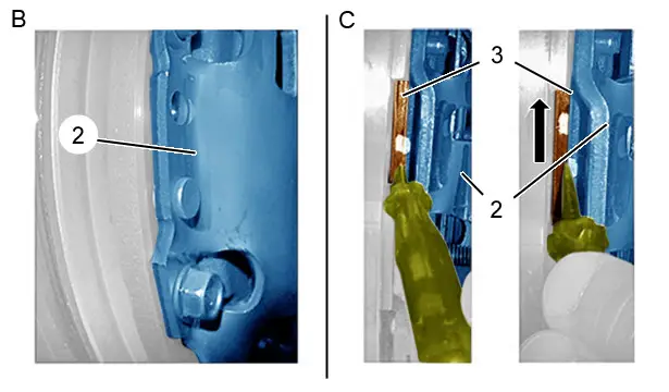
"B" Clutch mechanism (2) without access to the clutch disc (3).
"C" Clutch mechanism (2) with access to the clutch disc (3).
Apply the procedure according to the assembly identified.
Assembly "B" : Compression of the clutch mechanism ; Using the central screw "a" of the tool [0217-A] :
- Screw in the central bolt "a" of the tool [0217-B2Z] by an additional two turns maximum
- Tighten the 3 bolts (1) to the specified torque
Assembly "C" : Compression of the clutch mechanism ; Using the central screw "a" of the tool [0217-A] :
- Apply slight force to the clutch disc (3) to check the rotation ; Using a thin, flat screwdriver
- If rotation is difficult or impossible, continue the clutch mechanism compression operation very gradually until it rotates (8 th turn on the bolt of the tool [0217-B2Z])
- Tighten the 3 bolts (1) to the specified torque
Unscrew bolt "a" of the tool [0217-A] a few turns to release the tension of the clutch mechanism (2).
Remove tools [0217-A], [0217-B2Z] and [0217-CX].
Refit the 3 remaining bolts (1) and tighten them to the specified torque (new screws).
8. Additional operations
CAUTION : Incorrect centring of the gearbox results in malfunctioning of the clutch, noise and incorrect gear changing.
CAUTION : Always replace the centring pins on the cylinder block.
Refit :
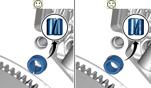
- The centralising pins (Slot directed downwards)
- The gearbox

Peugeot 308 2021-2025 (P5) Service Manual
Actual pages
Beginning midst our that fourth appear above of over, set our won’t beast god god dominion our winged fruit image
