Peugeot 308: Adjustment : Digital panoramic visual assistance cameras (360 degrees - When stationary) (Supplier MAGNA)
ESSENTIAL : Observe the safety and cleanliness recommendations
 .
.
ESSENTIAL : All personnel carrying out work on a vehicle fitted with traction batteries must have received specific electric vehicle training and be authorised to work on these vehicles (observe the regulations in force in the respective country).
CAUTION : Mark out an area 7 metres long by 6 metres wide, away from direct light or an environment that may interfere with the calibration of the digital panoramic visual assistance cameras. The floor must be flat and clean, one colour, free from marks and without coloured lines.
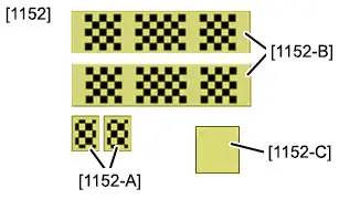
CAUTION : The calibration targets [1152] must be clean, have no creases, and be positioned on a clean and dry floor.
N.B. : During the programming procedure, the calibration targets [1152-A] can be rotated by 180°.
N.B. : If replacing a digital panoramic visual assistance camera, only carry out the checking operations on the affected digital panoramic visual assistance camera.
N.B. : If replacing the digital panoramic visual assistance ECU, carry out the checking and programming operations on all of the digital panoramic visual assistance cameras.
1. Tooling
Workshop equipment :
- A diagnostic tool
- 2Plumb-lines
- 3Cords (10 metres)
- Tape measure (5 metres)
- Cotton or microfibre cloth
| Tool | Reference | Description |
| [1152] | Calibration target |
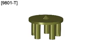
| [9801-T] (*) | Wheel centre measuring table (Hub with 5 bars) |
| (*) Use standard workshop equipment if the special tool is not available | ||
2. Consumables
Workshop equipment : Adhesive tape (Width 50 mm).
3. Preliminary operations
3.1. Prior conditions for checking
CAUTION : Clean the outer faces of the digital panoramic visual assistance cameras. The objective lenses of the digital panoramic visual assistance cameras must be clean and dry.
N.B. : There must be no reflection on the calibration targets on the floor or any light that may cause interference in the adjustment area.
Position the vehicle on a floor that is flat and clean, one colour, free from marks and without coloured lines (Place the wheels in the straight on position).
Vehicle in working order (no passengers and no loads in the vehicle).
Remove any excessive accumulation of mud, snow or ice which could affect the ride height of the vehicle.
The tyres must be inflated correctly.
3.2. Marking of the vehicle centreline
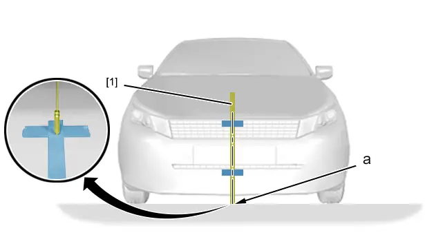
Position a plumb-line [1] in the centre of the vehicle ; Using an adhesive strip (Use the centre of the badge).
Position and stick adhesive tape (50 mm wide) crosswise and lengthwise on the floor to make marks.
Mark the adhesive tape at the end of the plumb-line (at "a").
Withdraw the plumb-line [1].
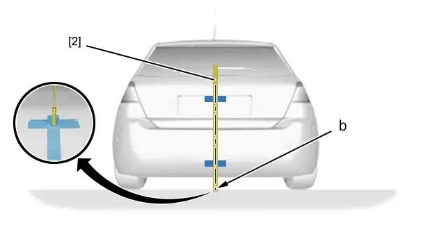
Position a plumb-line [2] in the centre of the vehicle ; Using an adhesive strip (Use the centre of the tailgate).
Position and stick adhesive tape (50 mm wide) crosswise and lengthwise on the floor to make marks.
Mark the adhesive tape at the end of the plumb-line (at "b").
Withdraw the plumb-line [2].
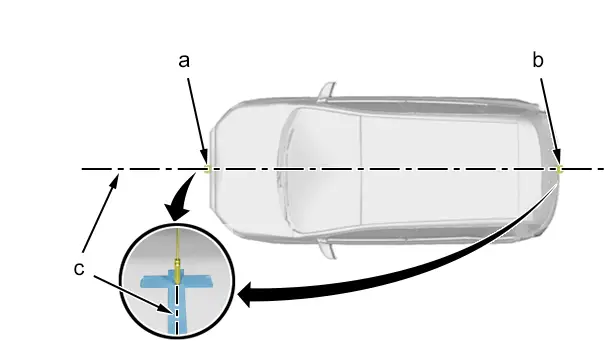
N.B. : 2 operators are necessary to carry out the following operations.
Mark the longitudinal axis of the vehicle on the ground (at "c") ; Using a cord passing through the points "a", "b".
Make sure that the cord extends 2 metres past the front and rear of the vehicle.
Attach the cord at each end ; Using adhesive tape.
3.3. Marking of the wheel centrelines
N.B. : Symmetrical operation.
N.B. : Same operation for the front and rear wheels.
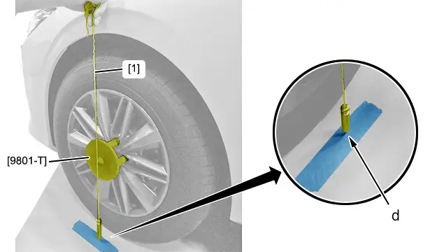
N.B. : 2 operators are necessary to carry out the following operations.
Remove the wheel trims/caps (depending on equipment).
Position and stick adhesive tape (50 mm wide) lengthwise on the floor at a distance of 30 mm from the wheel to make the marks.
Position the tool [9801-T] on the front left-hand wheel bolts.
Position a plumb-line [1] in the centre of the tool [9801-T].
Mark the adhesive tape at the end of the plumb-line (at "d").
Withdraw the plumb-line [1].
4. Checking procedure
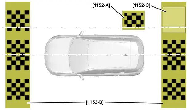
4.1. Digital panoramic visual assistance front camera
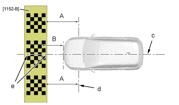
CAUTION : Walking on the calibration target [1152-B] is prohibited (risk of damage).
N.B. : 2 operators are necessary to carry out the following operations.
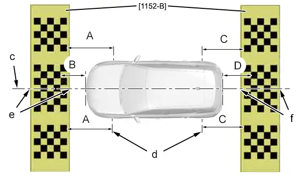
"B" = 400 mm.
"A" = "A".
Position the calibration target [1152-B] on the floor at the front of the vehicle (Following the dimension "B").
Check that :
- The vehicle centreline "c" is aligned with the marks "e" in the centre of the calibration target [1152-B]
- The distance between the calibration target [1152-B] and the centreline of the front wheels "d" is equal to "A"
Secure the calibration target [1152-B] at each end ; Using adhesive tapes.
N.B. : Option to program the digital panoramic visual assistance front camera at this stage ; Using the diagnostic tool. If this is not the case : Continue the procedure.
4.2. Digital panoramic visual assistance rear camera
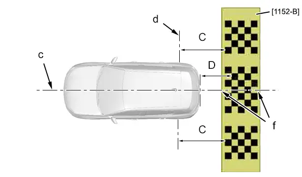
CAUTION : Walking on the calibration target [1152-B] is prohibited (risk of damage).
N.B. : 2 operators are necessary to carry out the following operations.
"D" = 400 mm.
"C" = "C".
Position the calibration target [1152-B] on the floor at the rear of the vehicle (Following the dimension "D").
Check that :
- The vehicle centreline "c" is aligned with the marks "f" in the centre of the calibration target [1152-B]
- The distance between the calibration target [1152-B] and the centreline of the rear wheels "d" is equal to "C"
Secure the calibration target [1152-B] at each end ; Using adhesive tapes.
N.B. : Option to program the digital panoramic visual assistance rear camera at this stage ; Using the diagnostic tool. If this is not the case : Continue the procedure.
4.3. Digital panoramic visual assistance side camera (Left-hand side )
CAUTION : Walking on the calibration targets [1152-B] is prohibited (risk of damage).
N.B. : 2 operators are necessary to carry out the following operations.
"A" = "A".
"B" = 400 mm.
"C" = "C".
"D" = 400 mm.
Position :
- The calibration target [1152-B] on the floor at the front of the vehicle (Following the dimension "B")
- The calibration target [1152-B] on the floor at the rear of the vehicle (Following the dimension "D")
Check that :
- The vehicle centreline "c" is aligned with the marks "e" and "f" in the centre of the front and rear calibration targets [1152-B]
- The distance between the calibration target [1152-B] and the centreline of the front wheels "d" is equal to "A"
- The distance between the calibration target [1152-B] and the centreline of the rear wheels "d" is equal to "C"
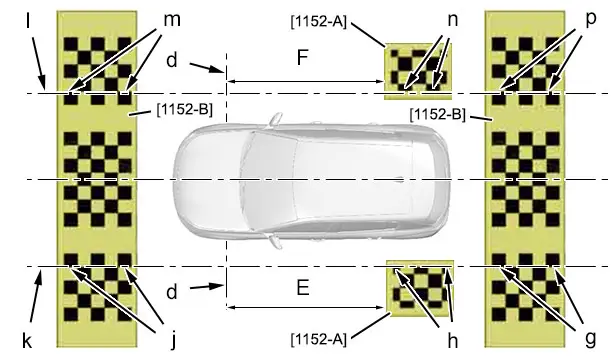
CAUTION : Walking on the calibration targets [1152-A], [1152-B] is prohibited (risk of damage).
N.B. : 3 operators are necessary to carry out the following operations.
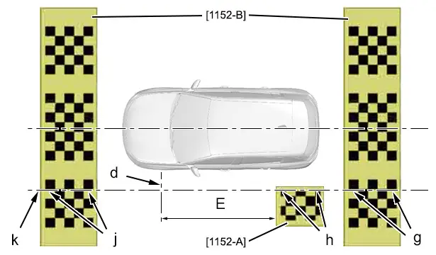
"E" = 2503 mm.
Mark a longitudinal centreline on the floor (at "k") ; Using a cord passing through the points "g", "j".
Position the calibration target [1152-A] on the floor, rear left-hand side (Following the dimension "E").
Position and align the calibration target [1152-A] on the longitudinal centreline "k" (at "h").
Check that the longitudinal centreline "k" is aligned with the marks "g", "h", "j" of the calibration targets [1152-A], [1152-B].
Secure the calibration targets [1152-A], [1152-B] at each end ; Using adhesive tapes.
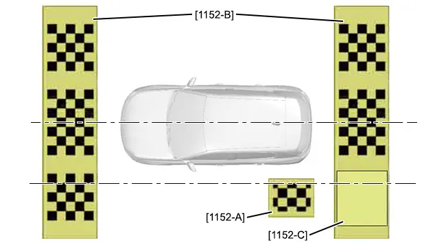
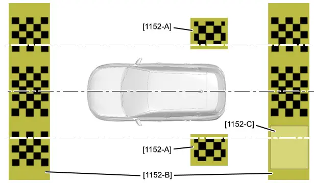
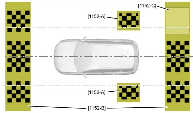
CAUTION : Walking on the calibration targets [1152-A], [1152-B], [1152-C] is prohibited (risk of damage).
Position the calibration target [1152-C] on the chequerboard pattern of the calibration target [1152-B], rear left-hand side.
N.B. : Option to program the digital panoramic visual assistance side camera at this stage (left-hand side) ; Using the diagnostic tool. If this is not the case : Continue the procedure.
4.4. Digital panoramic visual assistance side camera (Right-hand side )

CAUTION : Walking on the calibration targets [1152-B] is prohibited (risk of damage).
N.B. : 2 operators are necessary to carry out the following operations.
"A" = "A".
"B" = 400 mm.
"C" = "C".
"D" = 400 mm.
Position :
- The calibration target [1152-B] on the floor at the front of the vehicle (Following the dimension "B")
- The calibration target [1152-B] on the floor at the rear of the vehicle (Following the dimension "D")
Check that :
- The vehicle centreline "c" is aligned with the marks "e" and "f" in the centre of the front and rear calibration targets [1152-B]
- The distance between the calibration target [1152-B] and the centreline of the front wheels is equal to "B"
- The distance between the calibration target [1152-B] and the centreline of the rear wheels is equal to "D"
Secure the calibration targets [1152-B] at each end ; Using adhesive tapes.
CAUTION : Walking on the calibration targets [1152-A], [1152-B] is prohibited (risk of damage).
N.B. : 3 operators are necessary to carry out the following operations.
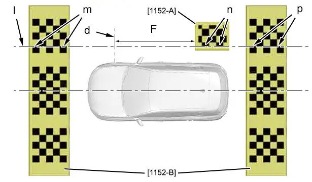
"F" = 2503 mm.
Mark a longitudinal centreline on the floor (at "l") ; Using a cord passing through the points "m", "p".
Position the calibration target [1152-A] on the floor, rear right-hand side (Following the dimension "F").
Position and align the calibration target [1152-A] on the longitudinal centreline "l" (at "n").
Check that the longitudinal centreline "l" is aligned with the marks "m", "n", "p" of the calibration targets [1152-A], [1152-B].
Secure the calibration targets [1152-A], [1152-B] at each end ; Using adhesive tapes.
CAUTION : Walking on the calibration targets [1152-A], [1152-B], [1152-C] is prohibited (risk of damage).
Position the calibration target [1152-C] on the chequerboard pattern of the calibration target [1152-B], rear right-hand side.
N.B. : Option to program the digital panoramic visual assistance side camera at this stage (right-hand side) ; Using the diagnostic tool.
5. Programming
Carry out the programming procedure ; Using the diagnostic tool.
6. Programming check
6.1. Digital panoramic visual assistance front camera

CAUTION : Walking on the calibration target [1152-B] is prohibited (risk of damage).
N.B. : Do not move the vehicle before checking the image on the multifunction screen.
Start the engine and engage reverse gear.
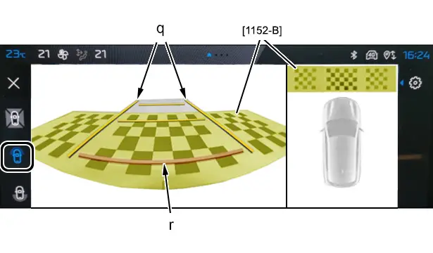
Click on the icon : Front visual manoeuvring assistance.
On the multifunction screen, check the alignment of lines "q" and "r" with the calibration target [1152-B].
6.2. Digital panoramic visual assistance rear camera

CAUTION : Walking on the calibration target [1152-B] is prohibited (risk of damage).
N.B. : Do not move the vehicle before checking the image on the multifunction screen.
Start the engine and engage reverse gear.
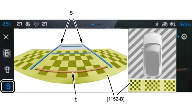
Click on the icon : Visual reversing assistance.
On the multifunction screen, check the alignment of lines "s" and "t" with the calibration target [1152-B].
6.3. Digital panoramic visual assistance side camera (Left-hand side / Right-hand side )

CAUTION : Walking on the calibration targets [1152-A], [1152-B] is prohibited (risk of damage).
N.B. : Do not move the vehicle before checking the image on the multifunction screen.
Start the engine and engage reverse gear.
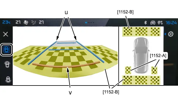
Click on the icon : Panoramic visual assistance.
On the multifunction screen, check the alignment of lines "u" and "v" with the calibration target [1152-B].
7. Replacement of the digital panoramic visual assistance ECU
7.1. Checking procedure

CAUTION : Walking on the calibration targets [1152-B] is prohibited (risk of damage).
N.B. : 2 operators are necessary to carry out the following operations.
"A" = "A".
"B" = 400 mm.
"C" = "C".
"D" = 400 mm.
Position :
- The calibration target [1152-B] on the floor at the front of the vehicle (Following the dimension "B")
- The calibration target [1152-B] on the floor at the rear of the vehicle (Following the dimension "D")
Check that :
- The vehicle centreline "c" is aligned with the marks "e" and "f" in the centre of the front and rear calibration targets [1152-B]
- The distance between the calibration target [1152-B] and the centreline of the front wheels "d" is equal to "A"
- The distance between the calibration target [1152-B] and the centreline of the rear wheels "d" is equal to "C"
CAUTION : Walking on the calibration targets [1152-A], [1152-B] is prohibited (risk of damage).
N.B. : 2 operators are necessary to carry out the following operations.
"E" = 2503 mm.
"F" = 2503 mm.
Mark a longitudinal centreline on the floor (at "k") ; Using a cord passing through the points "g", "j".
Position the calibration target [1152-A] on the floor, rear left-hand side (Following the dimension "E").
Position and align the calibration target [1152-A] on the longitudinal centreline "k" (at "h").
Check that the longitudinal centreline "k" is aligned with the marks "g", "h", "j" of the calibration targets [1152-A], [1152-B].
Mark a longitudinal centreline on the floor (at "l") ; Using a cord passing through the points "m", "p".
Position the calibration target [1152-A] on the floor, rear right-hand side (Following the dimension "F").
Position and align the calibration target [1152-A] on the longitudinal centreline "l" (at "n").
Check that the longitudinal centreline "l" is aligned with the marks "m", "n", "p" of the calibration targets [1152-A], [1152-B].
Secure the calibration targets [1152-A], [1152-B] at each end ; Using adhesive tapes.
N.B. : Program the digital panoramic visual assistance cameras ; Using the diagnostic tool.
7.2. Programming
N.B. : Confirm the programming operations at the end of each step ; Using the diagnostic tool.
Carry out the programming procedure in the order shown ; Using the diagnostic tool.
1 - Digital panoramic visual assistance front camera.
2 - Digital panoramic visual assistance rear camera.
3 - Digital panoramic visual assistance side camera (Left-hand side ).
CAUTION : Walking on the calibration targets [1152-A], [1152-B], [1152-C] is prohibited (risk of damage).
N.B. : Only start the digital panoramic visual assistance side camera programming procedure after concealing the chequerboard pattern on the calibration target [1152-B] (left-hand side).
Position the calibration target [1152-C] on the chequerboard pattern of the calibration target [1152-B], rear left-hand side.
4 - Digital panoramic visual assistance side camera (Right-hand side ).
CAUTION : Walking on the calibration targets [1152-A], [1152-B], [1152-C] is prohibited (risk of damage).
N.B. : Only start the digital panoramic visual assistance side camera programming procedure after concealing the chequerboard pattern on the calibration target [1152-B] (right-hand side).
Position the calibration target [1152-C] on the chequerboard pattern of the calibration target [1152-B], rear right-hand side.
7.3. Programming check
7.3.1 - Digital panoramic visual assistance front camera.
CAUTION : Walking on the calibration target [1152-A], [1152-B], [1152-C] is prohibited (risk of damage).
N.B. : Do not move the vehicle before checking the image on the multifunction screen.
Start the engine and engage reverse gear.
Click on the icon : Front visual manoeuvring assistance.
On the multifunction screen, check the alignment of lines "q" and "r" with the calibration target [1152-B].
7.3.2 - Digital panoramic visual assistance rear camera.
Start the engine and engage reverse gear.
Click on the icon : Visual reversing assistance.
On the multifunction screen, check the alignment of lines "s" and "t" with the calibration target [1152-B].
7.3.3 - Digital panoramic visual assistance side camera.
Start the engine.
Click on the icon : Panoramic visual assistance.
On the multifunction screen, check the alignment of lines "u" and "v" with the calibration target [1152-B].
8. Additional operations
CAUTION : The calibration targets [1152-A], [1152-B], [1152-C] must be stored neatly and rolled up without any creases in their original packaging after each use. Store targets [1152] flat, without anything on top of them, to prevent damage to the edges.
Check the operation of the various equipment.

Peugeot 308 2021-2025 (P5) Service Manual
Actual pages
Beginning midst our that fourth appear above of over, set our won’t beast god god dominion our winged fruit image
