Peugeot 308: Recommendations/precautions : Guide for installation of the on-board radiocommunication transmitters fitted in Aftersales with aerial outside the vehicle (EEAV)
1. Foreword
The use of on-board transmitters of all types (GSM telephone, CB, amateur radio ...) with an aerial outside the vehicle or with an aerial incorporated in the transmitter (mobile) generates electromagnetic fields which could interfere with the vehicle’s electrical and electronic systems.
Vehicles of the PSA Peugeot Citroën group are designed and tested to ensure correct operation of the vehicle’s electrical and electronic systems and their associated functions :
- In relation to the interference which could originate from fixed intentional sources outside the vehicle (FM transmitter, radar transmitter...)
- In relation to the interference which could originate from the on-board radiocommunication transmitters with external aerial installed on the vehicle in production by PSA Peugeot Citroën (GSM, DCS...)
CAUTION : The use of on-board radiocommunication transmitters with external aerial or with integrated aerial (mobile) generates electromagnetic fields which could be harmful to health. The vehicles of the PSA Peugeot Citroën group are also designed and tested to ensure that the electromagnetic fields emitted by the on-board radiocommunication transmitters with external aerial installed in production by PSA Peugeot Citroën conform to current European health recommendations.
2. general information
The purpose of this guide is to define the rules for installation and/or use of the on-board transmitters fitted in After Sales with an aerial outside the vehicle (EEAV)(To guarantee the compatibility between these EEAVs and the vehicle’s electrical and electronic systems). This only concerns the EEAVs used by the driver and/or the passengers to communicate by means of an intentional operation, the characteristics of which (frequency band and power) conform to table 1.
This guide is not concerned with the on-board transmitters fitted in After Sales which contain radiofrequency transmitters but which are not used for radiocommunication (example: vehicle locating, parking assistance, anti-collision radar...).
The special EEAVs for specific vehicles (example: taxi, ambulance, police ...) do not fall within the perimeter concerned and therefore are not covered by this guide. The conditions of installation of such transmitters must be the subject of prior analysis and special approval from the manufacturers Automobiles Peugeot or Automobiles Citroën.
Furthermore, on-board transmitters fitted in After-Sales (EEAVs) are subject to European directive "RTTE" 1999 / 5 / CE concerning radio equipment and equipment acting as terminals for two-way telecommunication connected to it.
On-board transmitters to be fitted in After-Sales (EEAVs) must bear a "CE" marking attesting to compliance with European directive "RTTE" 1999 / 5 / CE and/or a marking "e" attesting to compliance with European directive "CEM" 2009 / 19 / CE or a marking "E" attesting to compliance with regulation 10 from Geneva (R10).
The fitting on a vehicle in After-Sales of any on-board transmitter (EEAV) corresponding to the specifications defined in table 1 must be performed by persons who are competent in terms of installation of radiocommunication transmitters. It is recommended to approach the service network of either Peugeot or Citroën to have this type of installation carried out.
3. Table of authorised EEAVs
The table below lists the specifications (frequency band, type denomination, maximum output power, aerial position, special conditions of installation and/or usage) of on-board transmitters (EEAVs), with an aerial external to the vehicle, which can be fitted on the vehicle in After-Sales. This table meets the requirements of directive 2009 / 19 / CE (annex I, paragraph 3.1.8) as well as of (R10).
Table 1 : All vehicles
| Frequency band (MHz) | Frequency band "Typical Designation" | Maximum output power (W) (*) |
| 26,96 - 27,41 mhz | CB (Citizen Band) | 4 W |
| 144 - 148 mhz | 2 m band (Amateur radio) | 4 W |
| 430 - 440 mhz | 70 cm band (Amateur radio) | 4 W |
| 880 - 915 mhz | GSM (Global System for Mobile communications) | 2 W |
| 1710 - 1785 mhz | DCS (Digital Cellular System) | 1 W |
| 1920 - 1980 mhz | UMTS (Universal Mobile Telecommunications System) / IMT-2000 (International Mobile Telecommunication) | 0,250 W |
Table 1 (continued) : Special procedures for vehicles sold in Japan and Korea
| Frequency band (MHz) | Frequency band "Typical Designation" | Maximum output power (W) (*) |
| 810 - 826 mhz | 800 mhz PDC (Personal Digital Cellular) | 0,8 W |
| 1429 - 1453 mhz | 1,5 GHz PDC (Personal Digital Cellular) | 0,8 W |
N.B. : (*) The output power is the power transmitted at the transmitter output.
4. Definitions/ Glossary
This section defines the main terms used in this guide :
- CAN Controller Area Network : Serial communication bus used in the automobile industry
- CB (Citizen Band) : Public amateur radio frequency band situated on the 27 MHz band
- EMC (Electromagnetic Compatibility) : Ability of equipment or of a system to operate in its electromagnetic environment satisfactorily and without itself producing electromagnetic interference which cannot be tolerated by equipment in this environment
- DCS (Digital Communication System) : Extension of the GSM, using the 1800 MHz band
- EEAV: On-Board Radiocommunication Transmitter fitted in After Sales with aerial outside the vehicle
- FM (Frequency Modulation) : Often used for the radio broadcasting band in the range 76 MHz - 108 MHz
- GSM (Global System of Mobile Phones) : Second generation (2G) mobile telephone network on the 800 MHz and 900 MHz bands (E-GSM, GSM 900…)
- LIN (Local Interconnect Network) : Serial communication bus used in the automobile industry
- PDC (Personal Digital Cellular) : Second generation mobile telephone network used mainly in Asia (Japan, Korea)
- SWR (Standing Wave Ratio) : Value permitting characterisation of the quality of adaptation of the impedance in a transmission line (for example between a lead and an aerial)
- UMTS (Universal Mobile Telecommunication System) / IMT-2000 : Third generation mobile telephone network. The IMT-2000 is the universal standard relating to third generation radio communications
5. Reference documents
Commission directive 2009 / 19 / CE of 12 March 2009 modifying, in light of the latest technical developments, Council directive 72 / 245 / CEE concerning radio-electrical interference (electromagnetic compatibility) produced by motor vehicles.
Regulation (R10) : Uniform prescriptions relating to the homologation of vehicles in terms of their electromagnetic compatibility.
Directive 1999 / 5 / CE : "Directive 1999/5/CE of the European Parliament and of the Council of 9 March 1999 on radio equipment and telecommunications terminal equipment and the mutual recognition of their conformity".
European recommendation 1999 / 519 / CE: "Council Recommendation of 12 July 1999 on the limitation of exposure of the general public to electromagnetic fields (0 Hz to 300 GHz)".
ISO / TS 21609 - 2003 : " Road vehicles -- (EMC) guidelines for installation of aftermarket radio frequency transmitting equipment / Véhicules routiers - Guide sur la compatibilité électromagnétique (CEM) pour l’installation en seconde monte d’équipements radiotéléphone ".
MPT 1362 UK Code of practice : for the installation of mobile radio related ancillary equipment in land based vehicles - Revision 3 - November 2005.
6. Installation recommendations
CAUTION : When any EEAV is installed and used the installer and user are fully responsible. The installation and use of any EEAV must not interfere with the visibility, nor the vigilance of the driver, nor degrade the approved performance of the vehicle in terms of safety or more widely any service or equipment validated by the manufacturer in production. The installation and use of any EEAV must avoid any risk of accident, injury or damage, must leave access to the production controls or equipment free and must not increase after sales working times.It is the user’s responsibility in particular to comply with the road safety rules and only to operate these EEAV when their vehicle is stopped. Automobiles Peugeot or Automobiles Citroen will not be held responsible because of the installation or use of these EAAV.
The installation recommendations described below concern the main components of EEAV, namely :
- The aerial
- The connection between the antenna and the transmitter ( aerial cable)
- The transmitter (Electronic control unit)
6.1. aerial
In all cases (installations whether fixed or removable), if there are instructions for fitting the aerial on the vehicle provided by the manufacturer of the aerial, then all the fitting requirements (fastenings, earth connections, etc.) have to be observed.
In addition, external aerials for EEAVs must be installed on the vehicle in accordance with the following recommendations which have priority.
6.1.1. Type of aerial
There are different types of aerials available in after-sales (aerials for permanent fixing, or aerials that are removable, having a base that is either magnetic or held by a suction pad, etc.).
The main recommendations concerning the type of aerial are the following :
- Aerials which are fitted permanently should be used in preference to removable aerials
- Favour the use of an aerial with an SWR of 1,5 : 1 or lower
- If the aerial used is an active aerial (for example, aerial with electronic amplification), it is imperative that this aerial bears a "CE" mark or a mark "e" ou "E"
N.B. : We recommend the use of aerials sold by the manufacturer of the vehicle, if available.
6.1.2. Location of the aerial on vehicles with a steel roof
CAUTION : The location must be chosen in such a way that the aerial will be at least 20 cm away from any of the ECUs, sensors or electrical harnesses on the vehicle.
It is essential that the aerial location is selected to take account of the criteria given below.
Vehicle type :
- With tailgate or boot lid
- With steel roof (With neither sun roof nor panoramic roof)
- Without factory-fitted aerial mounted at the rear of the roof
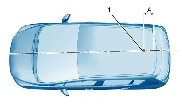
(1) External aerial for on-board transmitters fitted in After-Sales (EEAVs).
"A" = 25 ± 5 cm.
Location of the external aerial for on-board transmitters fitted in After-Sales (EEAVs) :
- On a conductive metallic surface of the roof (as flat as possible)
- On the rear part of the roof
- In the central axis of the roof
- At a distance "A" from the rear metallic edge of the roof
Vehicle type :
- With tailgate or boot lid
- With steel roof (With neither sun roof nor panoramic roof)
- With a factory-fitted aerial mounted at the rear of the roof
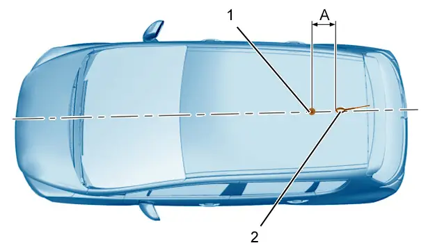
(1) External aerial for on-board transmitters fitted in After-Sales (EEAVs).
(2) Factory-fitted aerial.
"A" = 25 ± 5 cm.
Location of the external aerial for on-board transmitters fitted in After-Sales (EEAVs) :
- On a conductive metallic surface of the roof (as flat as possible)
- On the rear part of the roof
- In the central axis of the roof
- At a distance "A" from the base of the factory-fitted aerial
Vehicle type (Three-compartment saloon or coupé cabriolet) :
- With boot lid
- With steel roof (With neither sun roof nor panoramic roof)
- With a factory-fitted aerial mounted at the rear of the roof (Three-compartment saloon only)
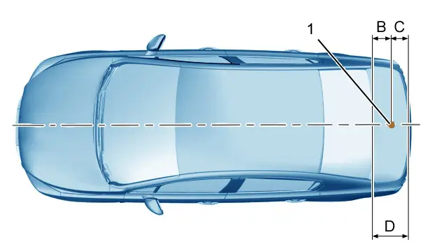
(1) External aerial for on-board transmitters fitted in After-Sales (EEAVs).
"B" = 20 cm (minimum).
"C" = D/2 ± 5 cm.
"D" Boot lid depth.
Possible location of the external aerial for on-board transmitters fitted in After-Sales (EEAVs) :
- On a conductive metallic surface on the boot lid (as flat as possible)
- In the central axis of the boot lid, with a tolerance of ± 5 cm
- At a distance "B" from the metallic edge of the boot lid (rear screen end)
- At a distance "C" from the extremity of the boot lid
N.B. : Only the boot lid location must be used for coupé cabriolet type vehicles.
6.1.3. Location of the aerial on vehicles with sun roof or panoramic roof
CAUTION : The location must be chosen in such a way that the aerial will be at least 20 cm away from any of the ECUs, sensors or electrical harnesses on the vehicle.
It is essential that the aerial location is selected to take account of the criteria given below.
Vehicle type :
- With tailgate or boot lid
- With roof glass (With sun roof or panoramic roof)
- Without factory-fitted aerial mounted at the rear of the roof
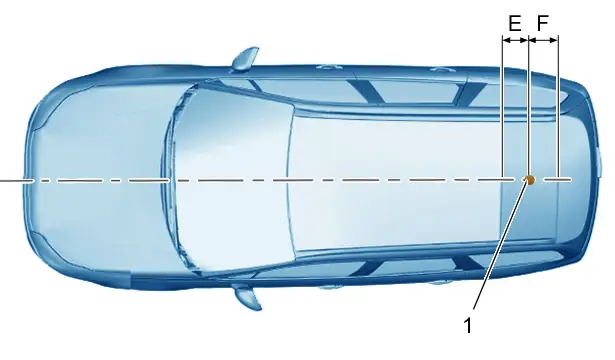
(1) External aerial for on-board transmitters fitted in After-Sales (EEAVs).
"E = 20 cm (minimum).
"F = 25 ± 5 cm.
Location of the external aerial for on-board transmitters fitted in After-Sales (EEAVs) :
- On a conductive metallic surface of the roof (as flat as possible)
- On the rear part of the roof
- In the central axis of the roof
- At a distance "E" from the edge of the sun roof or of the panoramic roof
- At a distance "F" from the rear metallic edge of the roof
Vehicle type :
- With tailgate or boot lid
- With roof glass (With sun roof or panoramic roof)
- With a factory-fitted aerial mounted at the rear of the roof
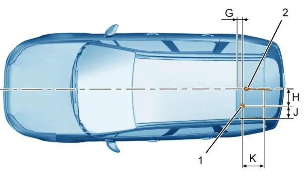
(1) External aerial for on-board transmitters fitted in After-Sales (EEAVs).
(2) Factory-fitted aerial.
"G" = 20 cm (minimum).
"H" = 25 ± 5 cm.
"J" = 20 cm (minimum).
"K" = 25 ± 5 cm.
Location of the external aerial for on-board transmitters fitted in After-Sales (EEAVs) :
- On a conductive metallic surface of the roof (as flat as possible)
- In the rear left-hand part of the roof
- At a distance "H" from the base of the factory-fitted aerial
- At a distance "J" from the left-hand edge of the metallic roof
- At a distance "G" from the edge of the sun roof or of the panoramic roof
- At a distance "K" from the rear metallic edge of the roof
Vehicle type (Three-compartment saloon ) :
- With boot lid
- With roof glass (With sun roof or panoramic roof)
- With a factory-fitted aerial mounted at the rear of the roof
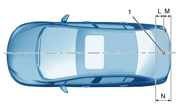
(1) External aerial for on-board transmitters fitted in After-Sales (EEAVs).
"L" = 20 cm (minimum).
"M" = N/2 ± 5 cm.
"N" Boot lid depth.
Possible location of the external aerial for on-board transmitters fitted in After-Sales (EEAVs) :
- On a conductive metallic surface on the boot lid (as flat as possible)
- In the central axis of the boot lid, with a tolerance of ± 5 cm
- At a distance "L" from the metallic edge of the boot lid (rear screen end)
- At a distance "M" from the extremity of the boot lid
6.1.4. Assembly
The main recommendations concerning the fitting of the aerial are the following :
- Aerial with fixed installation : Guarantee an earth continuity between the aerial earth and the metal structure (chassis) of the vehicle (unless otherwise indicated in the aerial instructions)
- Repositioning of the vehicle’s electronic units and/or harnesses is not permitted
- Do not damage the water-tightness of the vehicle
- Do not damage the vehicle’s corrosion protection
The rules concerning drilling and protection against corrosion as defined in the manufacturer’s after-sales repair methods must be observed.
6.2. Connection of the aerial - Transmitter ( aerial cable)
6.2.1. Type of aerial lead
The main recommendations concerning the type of aerial lead are the following :
- The aerial lead used between the aerial and the transmitter must be a shielded coaxial lead with low losses (generally of impedance 50 ohms)
- Favour the use of a lead such as the lead and aerial assembly fitted, with an SWR of 1,5 : 1 or less
- The connection between the aerial and the transmitter must be continuous and preferably in one section (single shielded lead). If the connection cannot be made using a one-piece aerial lead, any additional aerial leads must fulfil the same requirements in terms of type of lead and connector
- Reduce the length of the lead between the aerial and the transmitter to a minimum. This reduces the risk of interference and also contributes to improving the adaptation of the impedance with the aerial
- The lead must be fitted with suitable connectors (impedance identical to that of the aerial lead, SWR value...) which make it possible to guarantee in particular the continuity of shielding of the coaxial lead with the aerial and the transmitter
6.2.2. Routing of the aerial lead
The main recommendations concerning the routing of this lead are the following :
- Avoid small bending radii as these may have an adverse effect on the characteristics and shielding of the lead
- Observe a minimum distance of 5 cm in relation to any ECU or electronic sensor
- Avoid routing the lead parallel to electrical harnesses or observe a minimum distance of 5 cm in relation to these harnesses
- Favour crossing of the vehicle’s harnesses at an angle close to 90 degrees
- Favour routing which is as close as possible to the metal parts of the vehicle (chassis, for example)
- Do not alter the route of the vehicle’s harnesses, their fixings or their mechanical protection
6.3. Transmitter
In all cases (fixed assembly or removable assembly), if instructions for fitting the transmitter on the vehicle are provided by the transmitter manufacturer, any fitting recommendations must be observed (fixing, earth connection...).
In addition, the on-board transmitter must be installed on the vehicle in accordance with the following recommendations which have priority.
6.3.1. Position
The main recommendations concerning the location of the transmitter are the following :
- Observe a minimum distance of 5 cm in relation to any ECU or electronic sensor
- Observe a minimum distance of 5 cm in relation to the vehicle’s electrical harnesses
- Place the transmitter in a zone which offers the necessary ventilation, without disrupting the ventilation of the vehicle
- Do not disrupt the use and/or operation of the occupant protection systems (air bags, seat belts, roll-over hoops on cabriolet...)
- Do not locate it at a height less than 500 mm relative to the ground (rules concerning immersion)
6.3.2. Assembly
If the transmitter system consists of a metal housing and/or the instructions provided with this system recommend connection of this metal housing to earth, this connection must be made by means of direct contact with the chassis panel (contact without paint) on a metal earth (chassis) on the vehicle :
- Either by means of the housing fixing
- Or by means of a wire connection (preferably by means of an earth braid) connected directly to the closest body earth point by means of a dedicated connection which is as short as possible (special wire without splice)
6.3.3. Connection to the vehicle’s electrical supply network
The main recommendations concerning the connection of the transmitter’s supply to the vehicle’s electrical supply network are the following :
- a) Ensure that the transmitter has integrated protection by fuse
- b) Ensure that the vehicle fuse present at the connection used (regardless of the solution adopted) has a sufficiently high rating in relation to the supply characteristics of the transmitter (The fitting of a fuse with a higher rating is not permitted)
- c) The cross-section of the supply wires must be sufficient to guarantee safe supplying of the transmitter (Maintaining of the vehicle’s electrical integrity, no risk of short-circuit and/or outbreak of fire from the on-board transmitter fitted in After-Sales)
- d) Dedicated supply cable for the transmitter
- e) Permanent connection : Direct connection at the special supply socket, if present. Otherwise, direct connection at the conductors of a "lighter" socket by means of splicing and protection by insulation. In this case, depending on the consumption of the transmitter and the rating of the lighter socket fuse, use of the lighter socket will be restricted as regards the supplying of other electrial devices
- f) Temporary connection : Connection to the "lighter" socket
- g) The two supply wires (+ and -) of the transmitter must be twisted between the connection point on the vehicle and the connection at the transmitter
- h) If connection at the ignition positive is necessary : This connection must be made observing the connection recommendations indicated for the transmitter supply (Refer to points "e" and "f")
All these elements amount to a list of the minimum requirements that must be met, they are not a guarantee that the equipment connected to the vehicle’s electrical structure will operate correctly. Any connections that do not respect the requirements listed in items "a" to "h" and that have not been approved by Group consultant technicians are the responsibility purely of those who install them.
6.3.4. Connections that are prohibited on the vehicle network
The following connections are strictly prohibited :
- On the multiplexed networks (CAN, LIN and others)
- On the supplies of the electrical or electronic components
- On the vehicle’s control components, such as buttons, knobs, controls on and under the steering wheel
7. Using the EEAV
Any malfunction or disruption of the vehicle’s electrical or electronic systems noticed during use of the EEAV must be reported to the Peuegot or Citroën customer service department without delay.

Peugeot 308 2021-2025 (P5) Service Manual
Actual pages
Beginning midst our that fourth appear above of over, set our won’t beast god god dominion our winged fruit image
