Peugeot 308: New vehicle preparation : Instructions for use of the "E-XTEQ" battery tester
To meet the needs of Authorised Repairers and to repair current and future vehicles marketed by the STELLANTIS Group, a new 12 V ancillaries battery tester has been developed.
The new e-XTEQ battery tester (called DS ONE with the reference [CB-12123]MIDTRONICS) will be rolled out later this year to replace the brand’s models.
This tool is for testing all PCD/OV vehicles.
N.B. : This new battery tester must be used during a Pre-Delivery Inspection (PDI).
N.B. : MIDTRONICS codes/tickets will no longer be accepted as proof under 3-month warranty after the e-XTEQ (DS ONE) battery tester has been rolled out in the country.
1. Presentation
1.1. Roles of the e-XTEQ (DS ONE) battery tester
The policy for rolling out the new battery tester is in line with an approach to :
- Quality, as part of the STELLANTIS Group’s ancillaries battery checking policy
- Customer satisfaction upon delivery of the new vehicle (Pre-Delivery Inspection (PDI))
- Manufacturer warranty –Battery standard B20 0410
Advantages :
- To avoid any battery failures arising after handover to the customer
- To remove contraints on accessibility : Software specific to PSA enables a check to be made either on the ancillary battery terminals or on the remote terminals
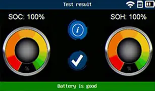
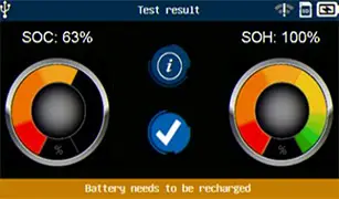
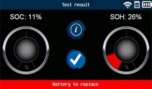
- Direct reading of the diagnosis on the battery tester (The battery is good ; The battery needs to be recharged ; The battery is to be replaced)
- Perform a diagnosis based on the reading of the voltage and the state of health of the ancillaries battery
- To justify credit claims under warranty
1.2. Presentation of the equipment
| Illustration | Business name of the e-XTEQ supplier | Tool part numbers |
| DS ONE battery tester | [CB-12123-] |
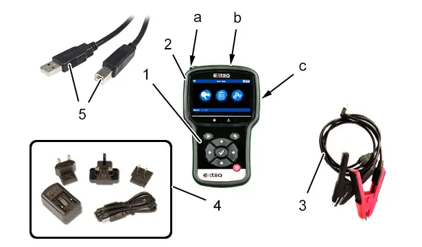
(1)e-XTEQ (DS ONE) battery tester.
(2)Impact-resistant protection.
(3)Cable with connection clamps.
(4)Tool charger with universal adapters.
(5)USB A/USB B adapter cable.
"a"Infrared temperature sensor.
"b"1D / 2D bar code scanner.
"c"USB socket A.
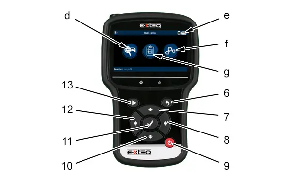
(6)Return.
(7)Up arrow.
(8)Right arrow.
(9)ON/OFF button.
(10)Down arrow.
(11)Validation button.
(12)Left arrow.
(13)Sub-menu validation button.
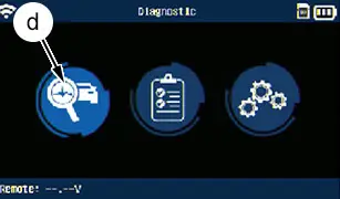
"d""diagnostic" menu.
"e"Charge status of the tester.
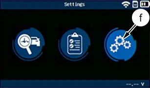
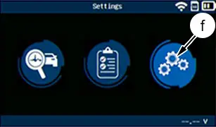
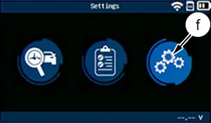
"f"Settings menu.
"g"Report history.
N.B. : The side buttons (8) and (12) are used to navigate the sub-menus (lower part of the screen).
CAUTION : The temperature during use has to be between 0 and 45°C.
1.3. Marketing of the e-XTEQ (DS ONE) tool
Marketing is controlled by the Replacement Parts department.
This battery tester is visible in the manufacturer’s aftersales documentation portal : "DOCUMENTATION" tab ↦Special tools ↦"Electricity - Diagnostic" family.
2. Periodic check of the e-XTEQ (DS ONE) battery tester
CAUTION : The periodic inspection is the responsibility of the owner of the e-XTEQ (DS ONE) battery tester.
Have the battery tester checked and calibrated every e-XTEQ (DS ONE) years in an official E-XTEQ approved technical centre.
3. Configuration of the e-XTEQ (DS ONE) battery tester
N.B. : When using the battery tester for the first time, the operator must register the tool in the OPTIMUS office software.
3.1. Choice of language
| Illustration | operation |
| Select the "Parameter" menu (In "f") |
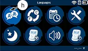
| Select the language setting menu (In "h") |
| Select the required language |
3.2. Selecting the units of measurement
| Illustration | operation |
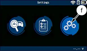
| Select the "Parameter" menu (In "f") |
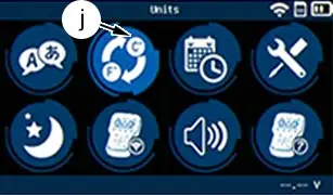
| Select the temperature units settings menu (In "j") |
4. Connection of the battery tester to the Wi-Fi network
4.1. Connecting to the Wi-Fi network for the first time
| Illustration | operation |
| Select the "Parameter" menu (In "f") |
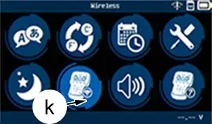
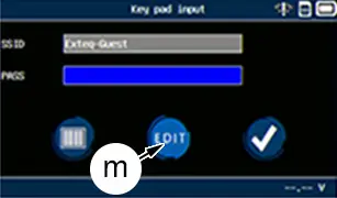
| Select the "Wireless" menu (In "k") |
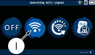
| Select the "Searching wifi signal" menu (In "l") |
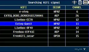
| Select the internal network (Example : Exteq-Guest) |
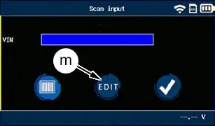
| Select the "EDIT" menu (In "m") |
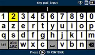
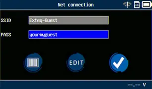
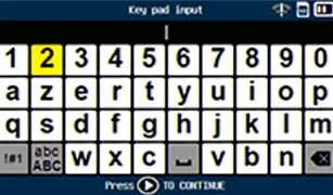
| Enter the password ;Using the alphanumeric keypad/!\ :Observe the case (upper, lower)Confirm ; Using the sub-menu validation button (13)) |
| Confirm ; Using the validation button (11) |
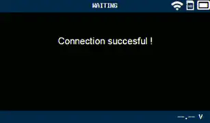
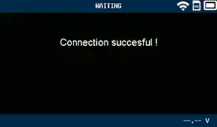
| Display of the message : Connection successfulConnecting to the ARGOS server database enables data to be transferred wirelessly |
4.2. Reconnecting to the Wi-Fi network
| Illustration | operation |
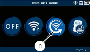
| When starting up the battery tester, the connection is not activeTo restore the previous connection, select "Reset wifi module" (In "n") |
| Display of the message : Connection successful |
5. Verification of the version number
N.B. : Warranty credit claims will only be taken into account if the tool e-XTEQ (DS ONE) has the latest update.
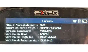
The version number is permanently available in "Version" :
- Select "Info" (In the Main Menu)
- Select "Version" (In the "Info" menu)
| Illustration | operation |
| Select the "Parameter" menu (In "f") |
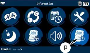
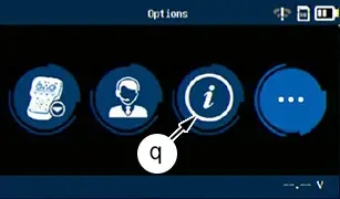
| Select "Info" (In "p") |
| Select the "about" menu (In "q") |
| Display of the e-XTEQ battery tester information |
N.B. : If the tool does not have the latest update installed, refer to the "Update of the battery tester" section.
6. Updating of the battery tester
6.1. Operation
N.B. : The need to update the battery tester is indicated by an icon on the screen of the tester.
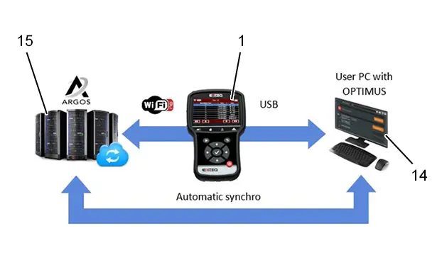
(1)e-XTEQ (DS ONE) battery tester.
(14)Computer with OPTIMUS office software.
(15)Server ARGOS.
Operation via USB connection :
- The battery tester sends the information to the computer
- The computer exchanges the information with the ARGOS server (Automatic synchronisation
- The ARGOS server updates the battery tester after validation by the user
Operation via Wi-Fi :
- The computer exchanges the information with the ARGOS server (Automatic synchronisation)
- The ARGOS server updates the battery tester after validation by the user
6.2. First use
When using it for the first time :
- An update of the battery tester is required via USB connection to the computer with OPTIMUS office software
- The battery tester is registered automatically in the ARGOS server
- The RRDI code can be entered
N.B. : The RRDI code is used to trace credit claims.
Procedure to be carried out in order to update the tool :
- Connect the battery tester to the computer ; Using the USB A/USB B adapter cable
- Launch the OPTIMUS office software
- Follow the office software procedure
6.3. Periodic update of the battery tester
N.B. : The need to update the battery tester is indicated by an icon on the screen of the tester.
Procedure to be carried out in order to update the tool via a wired connection :
- Connect the battery tester to the computer ; Using the USB A/USB B adapter cable
- Launch the OPTIMUS office software
- Follow the office software procedure
Procedure to be carried out in order to update the tool via Wi-Fi :
- Start up the battery tester
- Connect the battery tester to the internal Wi-Fi network
- Start the update
7. Preliminary operations
ESSENTIAL : Observe the safety and cleanliness recommendations
 .
.
For the measurement to be reliable, perform the battery test at the start of the PDI, respecting the following mode of operation :
- Check that the BSI shunt is in the "Park" position
 (PEUGEOT vehicles)
 - Switch on the ignition (**)
- Switch on the dipped headlamps
- Start the engine (***)
- Move the vehicle forwards into the inspection zone
- Release the bonnet using the bonnet release inside the vehicle
- Switch off the engine (****) : (Automatic extinction of the vehicle lamps (according to model)
- Switch on the ignition (**)
- Turn on the dipped beams, or place the air blower control in the intermediate position (For the following vehicles : PEUGEOT BIPPER, PEUGEOT BOXER)
- Wait 5 seconds
- Turn off the dipped beams, or stop the air blower (according to model)
- Switch off the ignition (*****)
- Switch off all the electrical consumers
- Get out of the vehicle
- Close the accesses (If accessing the ancillaries battery necessitates leaving one of the doors open, manually close the catch of the lock of the door involved, to decoy the electrical system)
- Wait 4 minutes
- Perform the battery test
N.B. : (*) According to version and equipment.
(**) The switching on of the ignition differs depending on the type of vehicle :
- Standard vehicle : Place the key in the "Ignition" position
- Vehicle with hands-free starting : Press the button "START" (Without pressing on the brake pedal (automatic gearbox) or on the clutch pedal (manual gearbox))
- Electric vehicle : Turn the key to "ON" or "MAR" (according to model)
(***) Starting the vehicle differs depending on the type of vehicle :
- Standard vehicle : Turn the key to position "Start"
- Vehicle with hands-free starting : Press on the brake pedal (automatic gearbox) or on the clutch pedal (manual gearbox), and press on the "START" button
- Electric vehicle : Turn the key to "START" or "AVV" and hold it in this position until the "READY" or "vehicle ready to move" indicator lamp is lit on the instrument panel (according to model)
(****) Stopping the vehicle differs depending on the type of vehicle :
- Standard vehicle : Turn the key to position "0"
- Vehicle with hands-free starting : Press the button "START"
- Electric vehicle : Turn the key to "OFF" or "STOP" (according to model)
(*****) The switching off of the ignition differs depending on the type of vehicle :
- Standard vehicle : Turn the key to position "0"
- Vehicle with hands-free starting : Press the button "START" (Without pressing on the brake pedal (automatic gearbox) or on the clutch pedal (manual gearbox))
- Electric vehicle : Press the button "START" (Without pressing on the brake pedal (automatic gearbox) or on the clutch pedal (manual gearbox)) (according to model)
CAUTION : When handing over to the customer is not done following the "New vehicle Preparation (PDI)", perform any checks on the ancillaries battery with the BSI shunt in the "customer" position.
N.B. : Note down the result of the checking of the ancillaries battery on the FFA (’loose items check sheet’) so as to guarantee traceability.
8. Recommendations to be followed
ESSENTIAL : Observe the safety and cleanliness recommendations
 .
.
CAUTION : Refer to the method : Check of the ancillaries battery.
9. Location of measurement points
Select the bleed menu: "Location test".
| Location of measurement points | Definitions | Technical justification |
| Ancillaries battery recharging terminals | The black clip is connected to the remote earth under the bonnet. The red clip is connected on the ancillaries battery positive terminal (In compliance with the procedure indicated in the user precautions) | Negative terminal of the ancillaries battery inaccessible |
| The red clip is connected to the remote positive terminal under the bonnet. The black clip is connected to the remote earth under the bonnet | The ancillaries battery is difficult to access as a result of being located in the boot or under the seat | |
| Ancillaries battery terminals | The 2 clips are connected directly on the ancillaries battery terminals |
10. Presentation of the Aftersales/Parts label
N.B. : (*) According to version and equipment.
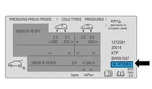
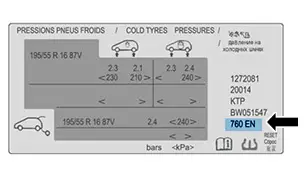
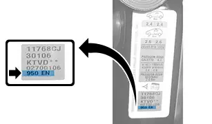
Types of Service and Parts labels / Manufacturer’s label (*)
| Illustration | Remarks |
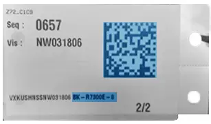
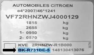
| First possibility: Label attached to the set of vehicle keys |
| Second possibility |
| Third possibility |
| Fourth possibility |
| Fifth option |
N.B. : Only the checks carried out using a BK code can be used to justify credit claims under warranty.
11. Test of the ancillaries battery in the vehicle, using the auto-configuration number(BK code)
N.B. : BK code : Auto-configuration number.
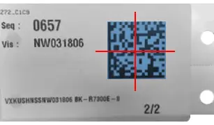
N.B. : Only valid for vehicles with an auto-configuration number on the Aftersales/Parts label or with the "data matrix code" on the label attached to the set of vehicle keys.
N.B. : Only the checks carried out using a BK code can be used to justify credit claims under warranty.
CAUTION : The accumulators of the battery tester should be charged up to avoid any risk of cut-off and the test being lost.
N.B. : To minimise the risk of inputting errors and unnecessary movements, start the operation near the Aftersales/Parts label or in possession of the label attached to the set of vehicle keys.
| Illustration | Operation and description |
| Select the "Diagnostic" menu (In "d") |
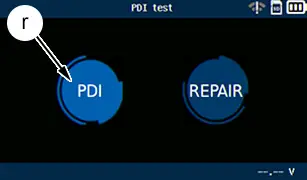
| Select the "PDI" menu (In "r") |
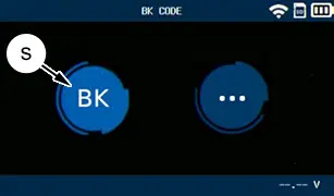
| Select the "BK" menu (In "s") |
11.1. First possibility : Reading of the "data matrix code"
| Illustration | Operation and description |
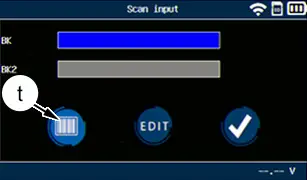
| Select the "bar code" menu (In "t") |
| Scan the "data matrix code" (Using the red aiming cross) |
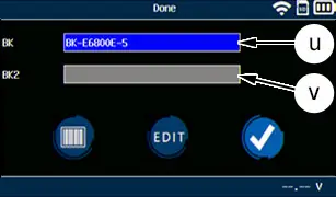
| Display of the ancillaries battery 1 auto-configuration number (In "u")Display of the ancillaries battery 2 auto-configuration number (In "v") (*)Confirm ; Using the validation button (11) |
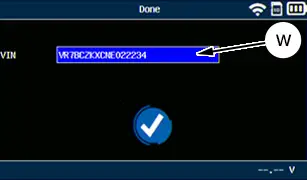
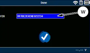
| Display of the VIN (In "w")Confirm ; Using the validation button (11) |
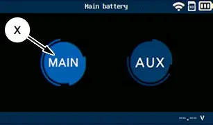
| For vehicles fitted with 2 ancillaries batteries, select the "MAIN" menu to check the ancillaries battery 1 (In "x") |
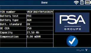
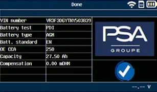
| If the VIN is in the database, the characteristics of the ancillaries battery are displayedConfirm ; Using the validation button (11) |
N.B. : The ancillaries battery 2 auto-configuration number is not used during a Pre-Delivery Inspection. Only the check via the diagnostic tool is validated.
11.2. Second possibility : Entering of the auto-configuration number
N.B. : BK code : Auto-configuration number.
| Illustration | Operation and description |
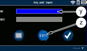
| Select the "EDIT" menu (In "z")Enter the auto-configuration number ;Using the alphanumeric keypad (In "y")Confirm ; Using the validation button (11) |
| Select the "EDIT" menu (In "m") |
| Enter the VIN ;Using the alphanumeric keypad/!\ :Observe the case (upper, lower)Confirm ; Using the sub-menu validation button (13) |
| Display of the VIN (In "w")Confirm ; Using the validation button (11) |
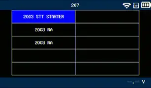
| Display of the list of vehicles corresponding to the self-configuration number of the ancillaries batterySelect a vehicleConfirm ; Using the validation button (11) |
| If the VIN is in the database, the characteristics of the ancillaries battery are displayedConfirm ; Using the validation button (11) |
12. Testing of the ancillaries battery in the vehicle
CAUTION : The accumulators of the battery tester should be charged up to avoid any risk of cut-off and the test being lost.
When the measurement of temperature is requested, position the battery tester 5 cm away from the ancillaries battery and do the temperature measurement.
N.B. : SOC : Ancillaries battery state of charge (state of charge).
N.B. : SOH :Ancillaries battery state of health (state of Health).
12.1. Case number 1: With layout image in the database
| Illustration | Operation and description |
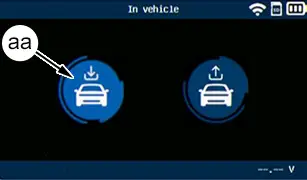
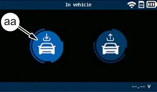
| Once the characteristics of the ancillaries battery have been selected with the BK code, the battery tester asks if the battery is inside or outside the vehicleSelect "IN THE VEHICLE" (In "aa") |
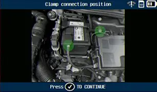
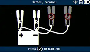
| Display of the layout image of the connection pointsConfirm ; Using the sub-menu validation button (13) |
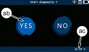
| Display of the "Start diagnostic?" screen when the voltage is detected and stable/!\ : A voltage value must be displayed in "ac"Click "YES" to start the diagnostic (In "ab") |
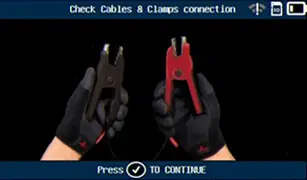
| Otherwise, display of the "Check Cables & Clamps connection" screenCheck the connectionsConfirm ; Using the sub-menu validation button (13) |
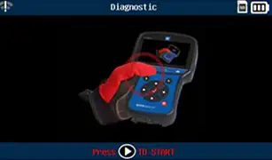
| Display of the "Diagnostic" screenPress to start the test ; Using the sub-menu validation button (13)) |
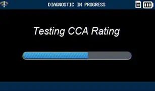
| Display of the "DIAGNOSTIC IN PROGRESS" screen |
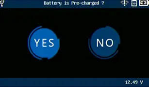
| Depending on the result of the diagnostic, display of the "Battery is Pre-charged?" screenSelect "YES" if the battery has been pre-charged before the diagnosticOtherwise select "NO" |
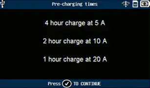
| If "NO" has been selected, display of the "Pre-charging times" screen indicating the charging time and the required currentConfirm ; Using the sub-menu validation button (13) |
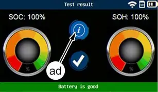
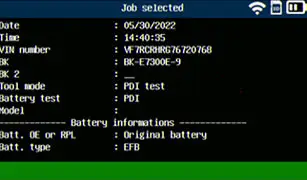
| Display of the "Test result" screenClick "i" to display the details of the diagnostic (In "ad") |
| Display of the result screenPress the button (6) to return to the result screen |
12.2. Case number 2: No layout image in the database
| Illustration | Operation and description |
| Once the characteristics of the ancillaries battery have been selected (with either the BK code or the VIN), the battery tester asks if the battery is inside or outside the vehicleSelect "IN THE VEHICLE" (In "aa") |
| Display of the "Battery terminal" screenConfirm ; Using the sub-menu validation button (13)Connect the battery tester to the ancillaries battery terminalsCheck the ancillaries battery |
12.3. Request to measure the temperature of the ancillaries battery
ESSENTIAL : /!\ : Do not point the laser beam at individuals or reflective objects.
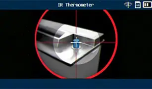
When the temperature measurement is requested, point the laser beam towards the ancillaries battery and take the temperature measurement.
| Illustration | Operation and description |
| The battery tester asks the operator to point the laser beam at one of the ancillaries battery terminals in order to take the temperature |
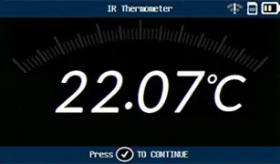
| Display of the temperature measurement result Confirm ; Using the sub-menu validation button (13) |
13. Actions recommended depending on the result displayed on the battery tester
| Illustration | Results | Action to be carried out |
| The battery is good | - |
| The battery needs to be recharged | Recharge the batteryRestart a test |
| The battery is to be replaced | Test the new ancillaries battery away from the vehicleReplace the battery |
14. Transfer of the results to the ARGOS server database
N.B. : All results can be automatically saved in the OPTIMUS office software via a connection to the Wi-Fi network.
| Illustration | Operation and description |
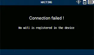
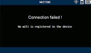
| Display of the "Connection failed" screen if the battery tester has lost the connectionSelect the "YES" icon to connect to the last Wi-Fi network access pointSelect the "NO" icon to return to the main screen |
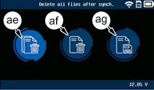
| The battery tester displays 3 choices :"ae" :Delete all results once they have been synchronised with the ARGOS server"af" :Only delete the results synchronised with the ARGOS server"ag" :Save the synchronised results to the internal memory of the battery tester |
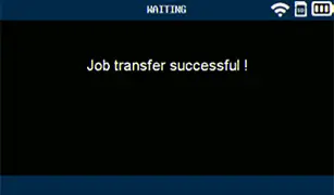
| Display of the message "Job transfer successful"The transferred results can be viewed via the OPTIMUS office software |
15. Error message
| Illustration | Operation and description |
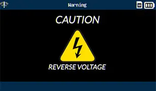
| Display of the message "REVERSE VOLTAGE", if the connection polarity is reversed |
| Display of the message "Connection failed" if a problem is detected with the connection to the Wi-Fi network when sending resultsRestart the procedure for connecting the battery tester to the Wi-Fi network |

Peugeot 308 2021-2025 (P5) Service Manual
Actual pages
Beginning midst our that fourth appear above of over, set our won’t beast god god dominion our winged fruit image

