Peugeot 308: New vehicle preparation : Special feature of technical preparation - 308 (P5) / e-308 (eP5) / 408 (P54) / 408 Malaysia (P54C)
N.B. : This method describes the operations in addition to the standard new vehicle preparation.
N.B. : (*) According to equipment.
1. Fitting the wheel trims
CAUTION : Failure to follow the removal/refitting procedure will result in significant damage to the wheel trims.
Refer to the removing-refitting method
 .
.
2. Presentation of the indirect tyre under-inflation system
A deflation detection is detected if the pressure is diminished by 20% relative to the pressures registered on initialisation.
Example :
- If the pressures in the vehicle’s front tyres are programmed at 2,4 bars, the tyre deflation alert will apply at around 1,9 bars
- If the pressures in the vehicle’s rear tyres are programmed at 2,2 bars, the tyre deflation alert will apply at around 1,8 bars
N.B. : The system does not locate which tyre is deflated.
3. Initialisation of the indirect tyre under-inflation detection system
CAUTION : Check the pressure of all the wheels before resetting the indirect tyre deflation detection system.
CAUTION : The under-inflation warning is only reliable if the resetting of the indirect tyre under-inflation detection system is requested with the pressure of the four tyres adjusted correctly.
N.B. : Any operation on the indirect deflation detection system, on the ESP ECU , or on the wheels, requires the indirect deflation detection system to be reset.
3.1. Location
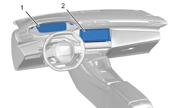
audio system / Audio-navigation with multifunction screen (touch) .
(1) Instrument panel .
(2) Multifunction touch screen.
Resetting of the indirect tyre under-inflation detection system is requested with the ignition on and the vehicle stationary.
3.2. Initialisation of the indirect tyre under-inflation detection system
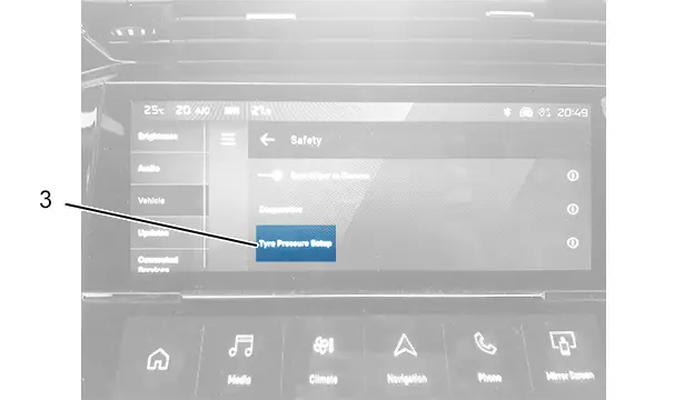
(3) "tyre under-inflation detection initialisation" touch button.
(4) Navigation arrows.
(5) "DRIVING" touch button.
Initialisation :
- Switch on the audio system
- Select the "Settings" menu : Using button "setting"
- Select the "Tyre under-inflation detection reset" menu (3)
- Confirm by pressing the " Reset " key
N.B. : An audible signal and a message confirm the reinitialisation.
N.B. : The new pressure parameters recorded are considered by the indirect tyre under-inflation detection system to be reference values.
4. Malfunction
| Display on the instrument panel | Remarks |
| Flashing then fixed lighting of the "Tyre under-inflation" warning lamp together with lighting of the "Service" warning lamp indicates a malfunction of the indirect tyre under-inflation detection systemIn the event of an indirect tyre under-inflation detection system malfunction, the tyre under-inflation detection is no longer activeHave the indirect tyre under-inflation detection system checked by the marque’s network or by a qualified workshop |

5. Key / Engine starting / Hands-free identifier
Check that the vehicle starts using all the keys.
Vehicle with hands-free starting (*).
CAUTION : The operator must have one hands-free identifier on him during the checking operations, the other hands-free identifier must remain more than 2 metres from the vehicle.
Check the functioning of the starting of the vehicle using the hands-free identifiers.
Check the functioning of the starting of the vehicle in hands-free mode.
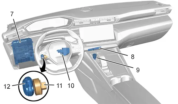
(7) Built-in systems interface.
(9) Engine starting switch.
(8) Dashboard interior aerial.
(10) Electric steering lock.
(11) Backup transponder aerial.
(12) Hands-free identifier.
Starting in customer mode :
- Position the gear lever on "P" or "N" and depress the brake pedal until the engine starts (Automatic gearbox)
- Depress the clutch pedal until the engine starts (manual gearbox)
- Press the engine starting switch (9) once
- The engine starts
N.B. : For diesel vehicles fitted with an engine starting switch and in sub-zero temperatures, starting is only possible after the pre-heating indicator lamp has gone off.
6. Openings and access
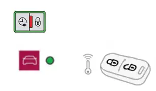
6.1. Check the hands-free access (*)
For vehicles with hands-free access : Perform the checks below on each of the keys.
The operator must have one hands-free identifier on him during the checking operations, the other hands-free identifier must remain more than 2 metres from the vehicle.
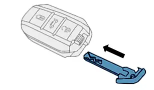
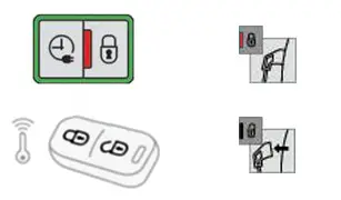
| Illustration | operation |
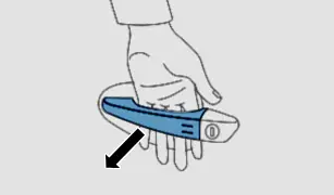
| Insert the mechanical insert in the hands-free identifierLock the vehicle using the buttons of the hands-free identifier |
| Unlock the vehicle doors using your handCheck that the lights flash when the doors are unlocked |
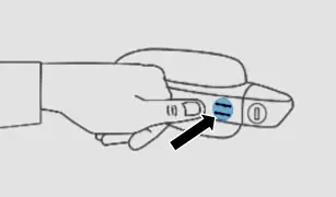
| Wait 2 seconds then lock the vehicle by pressing with one finger on the door handle (At the reference marks)Check that the lights come on when the doors are locked |
6.2. Reinitialisation of the motorised tailgate (*)
Fully open and close the motorised tailgate manually.
7. Checking the Stop and Start function (Internal combustion vehicle only)
At the end of the test, check the functioning of the STOP and START system (*).
Check that the engine switches to "STOP" mode :
- With a manual gearbox, put the gear control lever in neutral and release the clutch pedal (*)
- With a piloted manual gearbox, at a speed below 3 km/h, press the brake pedal or move the gear selector to position N (*)
- With an automatic gearbox, at a speed below 3 km/h, depress the brake pedal or move the gear lever to position N (*)
The engine stops and the "ECO" warning lamp lights up in the instrument panel.
N.B. : Conditions to be met for activation of STOP: Refer to the General Principles of Operation for the function.
Check the automatic restarting of the engine :
- With a manual gearbox, depress the clutch pedal (*)
- With a piloted manual gearbox / With an automatic gearbox: If the gear selector is in position A or M release the brake pedal, or if the gear selector is in position N and the brake pedal is already released move the gear lever to position A or M, or engage reverse gear (*)
The "ECO" warning lamp goes off and the engine restarts.
N.B. : The "ECO" warning lamp flashes 3 times if the conditions necessary for operation of the "Stop and Start" are not met.
8. Operations to be performed: After reconnecting the ancillaries battery
Procedure to be followed :
- Switch on the ignition
- Switch off the ignition
- Driving: Switch on the ignition ↦Start the engine ↦Drive and gradually increase the speed to at least 30 km/h over a distance of at least 50 m ; Ideally, the vehicle should be driving in a straight line
- Stop the vehicle
- Switch off the ignition
- Switch on the ignition
- Check that the "Collision risk detection system fault" warning message disappears from the instrument panel
- If the warning has disappeared ; Switch off the ignition
- If the warning is still present on the instrument panel ; Repeat the procedure from the driving stage
N.B. : When carrying out the road test, a subsequent dynamic test can be performed by continuing to drive and in doing so continuing the calibration procedure.
9. Checking the traction battery (Electric vehicle)
9.1. Checking the traction battery
CAUTION : Carry out the check every 30 days.
Procedure :
- Switch on the ignition
- Check the traction battery charge status on the instrument panel (As a percentage)
- If the value is less than 5%, charge the traction battery up to 10% (Approximately 18 minutes of charging in mode 2)
9.2. Traction battery charge level
CAUTION : When charging the traction battery, the traction battery and current transformation components cooling system is operational. The cooling fan is trigged based on the cooling requirements: this operating strategy is normal.
N.B. : Use of the mode 3 charging cable with an accelerated charging unit (Wallbox) is recommended for charging the traction battery to 100% before delivery to the customer.
10. Charging the traction battery
CAUTION : When charging the traction battery, the traction battery and current transformation components cooling system is operational. The cooling fan is trigged based on the cooling requirements: this operating strategy is normal.
N.B. : Use of the mode 3 charging cable with an accelerated charging unit (Wallbox) is recommended for charging the traction battery to 100% before delivery to the customer.
10.1. Installation and operation of the flap and the charging indicator lamps
9.1.1Location.
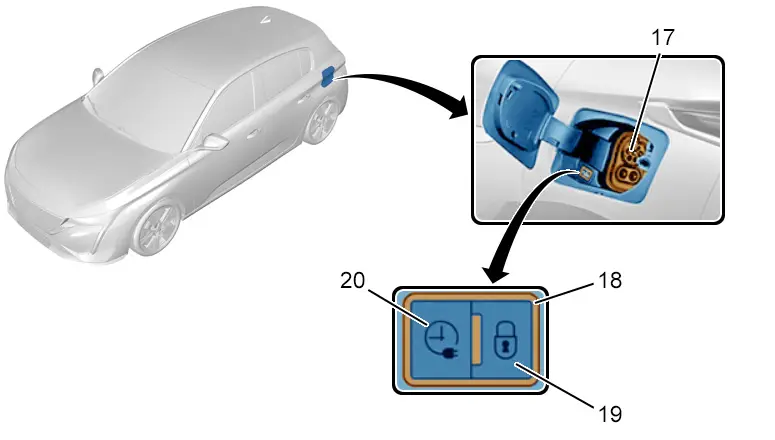
(17) Charging socket.
(18) Charging indicator lamp.
(19) Charging cable locking indicator lamp.
(20) Deferred charging activation button.
N.B. : When the charging cable locking indicator lamp lights up red, the charging cable is correctly positioned and locked in the charging socket.
9.1.2Operation of the charging indicator lamp.
| Colour of the warning lamp | Condition | Remarks |
| White | Fixed | Welcome lighting when opening the charging socket flap |
| Blue | Fixed | Deferred charging |
| Green | Flashing | Charging in progress |
| Green | Fixed | Charging complete |
| Red | Fixed | Malfunction |
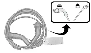
10.2. Charging cable
The mode 2 and mode 3 charging cables are supplied as standard with the vehicle.
N.B. : The charging cables supplied with the vehicle are compatible with the electrical installations of the country of sale.
10.3. Connecting the charging cables and traction battery charging modes
ESSENTIAL : Do not damage the charging cable and keep it intact ; In the event of damage, do not use the charging cable and contact the network or a qualified workshop to replace it.
CAUTION : Before charging, check that the sequential gear lever is in "P" mode and the ignition is off. If not, charging cannot be carried out.
Press on the charging flap opening control to open the charging flap.
Check that there are no foreign bodies on the charging socket unit.
CAUTION : When the traction battery has finished charging but the charging cable is still connected, opening the driver’s door will restart charging for approximately 20 seconds.
N.B. : For safety reasons, the engine will not start if the charging cable is connected to the vehicle charging socket unit. A warning message is displayed on the instrument panel.
Press on the charging flap opening control to open the charging flap.
9.3.12 mode (With charging cable supplied as standard) .
| Illustration | Description |
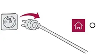
| Charging cable with integrated control unit |
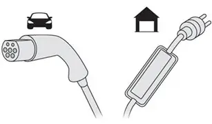
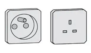
| Illustration | Domestic socket : Domestic charge |
| Mode 2 with a standard domestic socket : - Charge limited to 8 A maximum |
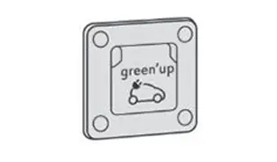
| Mode 2 with a Green'Up socket : - Charge limited to 16 A maximum |
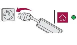
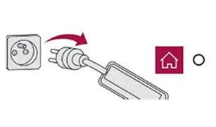
| Illustration | Connections |
| - Connect the charging cable on the control unit side to the mains socket or to the "Green'Up" socketOnce connected, all the control unit indicator lamps will come on. Only the green "POWER" control unit indictor lamp will stay on |
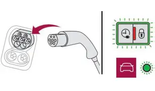
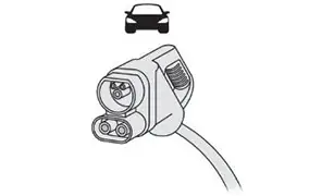
| - Remove the charging connector protective cover- Connect the charging connector to the charging socket unitThe "CHARGING" indicator lamps on the charging socket unit, and subsequently the control unit, flash green to confirm that charging has begunIf this does not occur, charging has not begun ; Check that all the connections are correct and repeat the stepsIf the red charging socket unit indicator lamp lights up, the charging connector is locked |
| Illustration | Unplugging |
| Charging is complete when the green "CHARGE" indicator lamp on the control unit stays on fixedBefore disconnecting the charging connector from the charging socket unit: ↦If the vehicle is unlocked, lock it and then unlock it ↦If the vehicle is locked, unlock it |
| If the red charging socket unit indicator lamp turns off, the charging connector is unlocked- Disconnect the charging connector within 30 seconds- Put the charging connector protective cover back on- Close the charging flap |
| - Disconnect the charging cable from the mains socket or the "Green'Up" socket (Control unit side)The green lamp "POWER" goes out |
9.3.23 mode (With charging cable supplied as standard) .
| Illustration | Description |
| Charging cable without an integrated control unit |
| Illustration | Accelerated charging unit (Wallbox) : - Rapid charge - Single-phase and three-phase alternating current |
| Mode 3 with an accelerated charging unit (Wallbox) : - Charge limited to 32 A maximum(According to version ) |

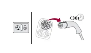
| Illustration | Connections |
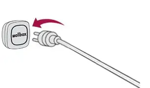
| - Connect the charging cable to the (Wallbox) accelerated charging socket(Follow the (Wallbox) accelerated charging socket instructions) |
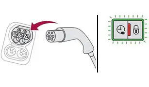
| - Remove the charging connector protective cover- Connect the charging connector to the charging socket unitThe green "CHARGING" indicator lamp on the charging socket unit flashes to confirm that charging has begunIf this does not occur, charging has not begun ; Check that all the connections are correct and repeat the stepsIf the red charging socket unit indicator lamp lights up, the charging connector is locked |
| Illustration | Unplugging |
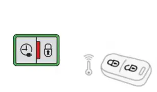
| Charging is complete when the green "CHARGING" indicator lamp on the charging socket unit stays on fixedBefore disconnecting the charging connector from the charging socket unit: ↦If the vehicle is unlocked, lock it and then unlock it ↦If the vehicle is locked, unlock it |
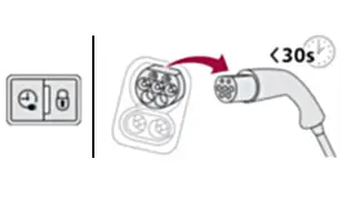
| If the red charging socket unit indicator lamp turns off, the charging connector is unlocked- Disconnect the charging connector within 30 seconds- Put the charging connector protective cover back on- Close the charging flap |
| - Disconnect the charging cable from the mains socketThe green lamp "POWER" goes out |
9.3.34 mode (Rapid charging public terminal) .
| Illustration | Description |
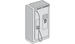
| Charging cable integrated into the public terminal |
| Illustration | Rapid charging public terminal : - Rapid charge - Direct current |
| Mode 4 with a rapid charging public terminal |
| Illustration | Connections |
| - Remove the charging connector protective cover (*) - Connect the charging connector to the charging socket unitThe green "CHARGING" indicator lamp on the charging socket unit flashes to confirm that charging has begunIf this does not occur, charging has not begun ; Check that all the connections are correct and repeat the stepsIf the red charging socket unit indicator lamp lights up, the charging connector is locked |
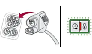
| Illustration | Unplugging |
| Charging is complete when the green "CHARGING" indicator lamp on the charging socket unit stays on fixedBefore disconnecting the charging connector from the charging socket unit: ↦If the vehicle is unlocked, lock it and then unlock it ↦If the vehicle is locked, unlock it- Disconnect the charging connector within 30 seconds- Put the charging connector protective cover back on (*) - Hang the connector on the rapid charging public terminal- Close the charging flap |
10.4. Indicative charging times
Charging time for a 50 kW traction battery
| Charging mode | KW of the electrical source ( Maximum amperage) | Battery charging time with a 7,4 kW OBC (As standard) | Battery charging time with a 11 kW OBC (Optional) |
| 2 mode (Domestic charge) | 1,8 kW (8 A maximum) | More than 24 hours | More than 24 hours |
| 2 mode (Domestic charge) | 3,2 kW (14 A maximum) | 16 hr 30 (Green'Up socket) | 16 hr 30 (Green'Up socket) |
| 3 mode (Rapid charge) | 3,7 kW (16 A maximum) (1 phase and 1 neutral) | 14 hr 30 | 14 hr 30 |
| 3 mode (Rapid charge) | 7,4 kW (32 A maximum) (1 phase and 1 neutral) | 8 hours | 8 hours |
| 3 mode (Rapid charge) | 11 kW (16 A maximum) (3 phases and 1 neutral) | 14 hr 30 | 5 hours |
| 3 mode (Rapid charge) | 22 kW (32 A maximum) (3 phases and 1 neutral) | 8 hours | 5 hours |
| 4 mode (Rapid charge) | 50 kW | 55 minutes (80% charged) | 55 minutes (80% charged) |
| 4 mode (Rapid charge) | 100 kW | 30 minutes (80% charged relative to the SOC) (*) | 30 minutes (80% charged relative to the SOC) (*) |
N.B. : (*) : SOC = State of Charge / Charge level.

Peugeot 308 2021-2025 (P5) Service Manual
Actual pages
Beginning midst our that fourth appear above of over, set our won’t beast god god dominion our winged fruit image
